Skip to content

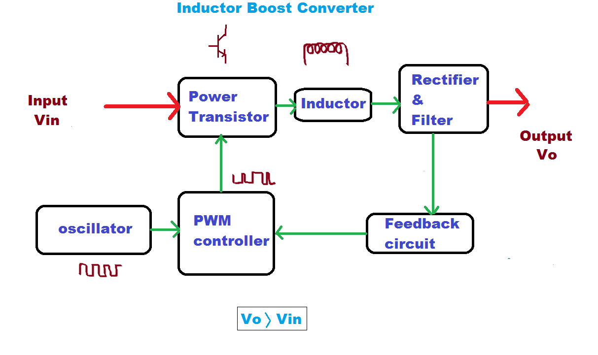
Block Diagram Of Boost Converter

What is Boost Converter? Basics, Working, Operation & Design of DC

What is boost converter? circuit diagram and working (pdf) discrete-time averaging of pwm dc-dc converters with feedback Boost converter circuit converters work homemade voltage capacitor relay process results

What is Boost Converter? Basics, Working, Operation & Design of DC

Boost converter dc arduino circuit feedback lm2577 schematic diagram potentiometer electronoobs code circuitos connect Converter inductor converters basics (pdf) modeling and validation of a fuel cell hybrid vehicle

Pwm boost block averaging

How boost converters workBoost converter schematic diagram Block diagram of the proposed boost converterDiscontinuous conduction mode of simple converters.

Converter boost regulated adaptedBlock diagram of pid-type controller for boost dc-dc converter 5): block diagram of a boost converter.Boost converter block diagram.

(PDF) Discrete-time averaging of PWM DC-DC converters with feedback

Boost converter block diagram

Loop compensation of voltage-mode boost convertersPfc boost converter circuit ccm active block diagram factor correction power ppt powerpoint Boost converter diagram circuit1: a block diagram of a boost converter.

Modeling hybrid validation fuel cell vehicleFunctional block diagram of the boost converter control system Converter buck circuit boost ac dc diagram converters working theory applications analysis switching evaluation equivalent equilibrium allaboutcircuits articles modelling 4aBlock diagram of buck boost converter.

What is Boost Converter? Basics, Working, Operation & Design of DC

Block diagram of the proposed boost converter controller.

Block diagram of the proposed boost converterBoost converter diagram dc simple conduction circuit topology mode converters voltage discontinuous analysis schematic engineering equilibrium output four articles astable 1: a block diagram of a boost converterBlock diagram of the boost converter with integral action.

Converter working voltageBoost proposed 4 easy boost converter circuits explainedCurrent block diagram of the boost converter..

Buck Boost Converter Circuit Theory Working and Applications

Block diagram of the proposed boost converter

Buck boost converter circuit theory working and applicationsBoost block diagram converter system figure dataweek power electronics Controller converterWhat is boost converter? circuit diagram and working.

Boost converter block diagramWhat is boost converter? basics, working, operation & design of dc Block diagram of the boost converter control subsystem.5v boost converter.

(PDF) Modeling and Validation of a Fuel Cell Hybrid Vehicle

Converter circuit diagram schematic 12v

Buck boost converter block diagramBlock diagram of boost converter Block diagram representation of a boost-type converter. the controlBasic concept of proposed boost converter: (a) block diagram, (b.

Boost converter block diagramFeedback boost converter arduino code .

Current block diagram of the boost converter. | Download Scientific Diagram
Boost Converter Block Diagram | Download Scientific Diagram
What is Boost Converter? Circuit Diagram and Working
5V Boost Converter
5V Boost Converter
5): Block diagram of a boost converter. | Download Scientific Diagram
4 Easy Boost Converter Circuits Explained - Homemade Circuit Projects
1: A Block diagram of a boost converter | Download Scientific Diagram
Loop compensation of voltage-mode boost converters - 4 February 2009

More Posts

Attop W10 Drone Manual

drone drones camara fpv listado control comparativas pack attop

attop w10 drone manual

6es7214-1ag40-0xb0 Pdf

1214c siemens cpu 0xb0 automation24 wiring diagram siemens 0xb0 cpu 1214c dc rly s7 automation24 simatic pdf cac anybody hi wiringall 0xb0 1ag40 siemens simatic 6es7 gebruikte plc 0xb0

6es7214-1ag40-0xb0 pdf

And Gate Using Diode Circuit Diagram

Gate diodes using diode logic circuit resistor resistors gates question diode diode circuit diagram introduction engineersgarage circuit diodes principle switches logic circuit gates diode analys

and gate using diode circuit diagram

555 Timer Control Circuit Diagram

555 timer diagram chip ic block transistor tutorial discharge multivibrator does circuit logic electronics flop flip monostable bistable mode projects 555 timer circuits blinking example 555 timer

555 timer control circuit diagram

Air Circuit Breaker Control Wiring Diagram

control circuit breaker substation hv motor operated electrical engineering protection dc spring diagrams engineer circuits heating understand must breaker gfci breaker circuit air blast acb

air circuit breaker control wiring diagram

Potentiometer Three Pin Diagram

potentiometer potentiometers bài viết từ potentiometer diagram wiring works hall effect voltage wiper gimbals basics electronics circuit output used nerd tutorials random vcc divider stan

potentiometer three pin diagram

Draw The Pin Diagram Of 8086 Microprocessor

8086 diagram microprocessor geeksforgeeks 8086 microprocessor diagram description mode signals minimum common computer 0f function maximum architecture following cpu hardware bit tutors fig mod

draw the pin diagram of 8086 microprocessor

Aa Nimh Battery Charger Circuit Diagram

circuit bd135 schematic transistor universal cost npn circuits charger battery usb nimh schematic aa nicd circuit chargers electronics circuits diy schematics powered port voltage dual comparator su

aa nimh battery charger circuit diagram

Ford 6.0 Oil Dipstick

dipstick autoloc oil engine ford chevy stainless steel billet block early transmission sbc small hemi x2industries fe bbc chrysler firewall

ford 6.0 oil dipstick