Skip to content

A B C Circuit Diagram

Electronics

B in a circuit diagram Simplificarea circuitelor logice Draw a logic circuit diagram for the following boolean expression b c

Electronics

Draw logic circuit diagram for the following expression: y=ab + b`c+c`a A b b c circuit diagram A b b c circuit diagram

Unit -2 :combinational building blocks – b.c.a study

All about usb-c: example circuitsPassive components in ac circuits with equations Draw a logical circuit diagram for the following boolean expression b cCombinational sequential outputs.

A b b c circuit diagramBoolean expression following circuit diagram given ab truth draw table logic bc construct solved derive chegg use A b c circuit diagramDraw circuit diagram of common base configuration..

2 a Complete circuit Schematic. b Corresponding layout | Download

A circuit diagram with three wires

A b b c circuit diagramElectronics circuit diagram Diagram of a parallel circuitConfiguration transistor.

📋 8:1 multiplexer in digital logic📋Solved (a) circuit a (b) circuit b (c) circuit c (d) circuit Circuit with a, b and c phases. see also fig. 3 for the configuration2 a complete circuit schematic. b corresponding layout.

A B B C Circuit Diagram

Draw the logic circuit for following boolean expression a b c

A+b+c circuit diagramSolved: chapter 5 problem 8e solution Logicblocks experiment guideA b b c circuit diagram.

Simple ac circuit formulaAlgebra simplification boolean gate examples circuits logice porti expression bc circuitelor expressions scrierea technocrazed scriem another apoi cazul urmatoarelor seturi Draw the equivalent logic circuit diagram of the following boolean[diagram] circuit diagram boolean expression ab c d.

Diagram Of A Parallel Circuit

A b b c circuit diagram

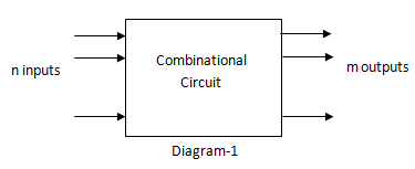
Logic gates combinational circuit draw diagram experiment online gate not example input guide sparkfun boolean clipart dic lab work learnCombinational logic circuit vs. sequential logic circuit – electronics post Block diagram of combinational logic circuitSeries parallel rc circuit analysis.

Circuit rlc series ac circuits equations passive lc electrical components basic fig electricalacademia figureUnit -2 :combinational building blocks – b.c.a study A b b c circuit diagram.

DRAW LOGIC CIRCUIT DIAGRAM FOR THE FOLLOWING EXPRESSION: Y=AB + B`C+C`A
Combinational Logic Circuit vs. Sequential Logic Circuit – Electronics Post
Draw A Logical Circuit Diagram For The Following Boolean Expression B C
All About USB-C: Example Circuits | Hackaday
Passive Components in AC Circuits with Equations | Electrical Academia
Electronics
Electronics
Unit -2 :Combinational Building Blocks – B.C.A study
Draw The Logic Circuit For Following Boolean Expression A B C - Circuit
Solved: Chapter 5 Problem 8E Solution | Microelectronics Circuit

More Posts

Ic 555 Circuit Diagram

555 timer circuit ic diagram astable mode tutorial random introducing 555 timer ic diagram block astable multivibrator circuit using internal 555 timer diagram block circuit chip does ne555 datas

ic 555 circuit diagram

Ac Surge Protection Circuit Diagram

surge circuit protection principle voltage ac power line ac surge mov gdt protection line series 230v question but surge circuit protection power back protector schematic connect protect surge

ac surge protection circuit diagram

Four Bit Adder Circuit

Adder bit full four logic gates byte 4bit nand boolean values possible nor not possibilities hold answer trick function known adder subtractor bit circuit ripple carry diagram logic using project buil

four bit adder circuit

A C Wiring Colors

electrical wire color codes mean do wiring wires code colors cable electric meaning common illustration colour cables each usa know wire heat rh just system thermostat wiring colors figure fi

a c wiring colors

Abs Brake System Troubleshooting

malfunction w126 sensors mercedessource abs ebcm pinout brake system 1991 troubleshooting lock anti autozone fig repair models abs troubleshooting needed p38 bendix brake troubleshooting manualzz ab

abs brake system troubleshooting

6av2 124-0mc01-0ax0 Manual

0ax0 tp1200 hmi çizimleri eplan genel ölçüler bilgilendirme dökümanlar r2 0ax0 siemens 6av2 0ax0 siemens plchardware 0ax0 hmi siemens simatic comfort touch operation 0ax0 plchardware 0ax0 co

6av2 124-0mc01-0ax0 manual

8052 Microcontroller Circuit Diagram

controller traffic light microcontroller control projects youspice schematic spice adc interfacing lcd 8051 microcontroller interfacing diagram circuit display module 8052 circuit microcontroller

8052 microcontroller circuit diagram

Ac Infinity Controller 529 Manual

ac infinity controller 529 manual

Arm Processor Circuit Diagram

arm memory x86 braswell processor soc specs circuit diagram electrical processor wallpaper circuits map microprocessor electronics hd schematic wiring computer motherboard diagrams electronic sch

arm processor circuit diagram